Measurement of lumped thermal conductance of a Warré hive
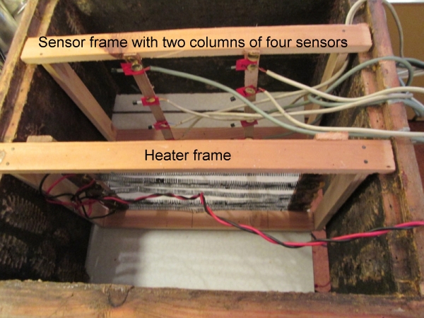
The method of Mitchell (2016) was applied to a two-box Warré hive. The hive was equipped with a top-bar cloth, quilt filled with planer shavings, Warré floor and roof. The boxes were made of 25 mm larch and both were fitted with top-bars. Frames were used for mounting the heater and sensors in the top box, substituting for two top-bars. As in Mitchell's study, the sensors were positioned at 8, 67, 124 and 181 mm below the top of the frame which in the present study had a top-bar 10 mm thick. The heater (12.5 watts) comprised four pairs of resistance wire coils wired in parallel (~5 ohms) and mounted in a frame so that the bottom of the heater was 195 mm from the top-bar cloth, thus 5 mm higher than in Mitchell's study.
Below: Warré box with heater and sensor frames illustrating the positioning at one third and two thirds of the width
The heater was surrounded by a radiant heat shield made of kitchen foil.
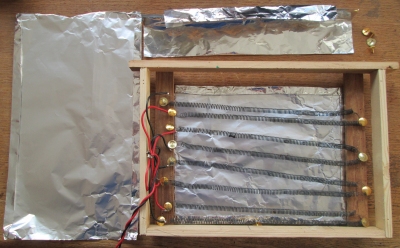 Left: heater with
top and side radiant heat shield removed
Left: heater with
top and side radiant heat shield removed
The equipment was allowed to reach thermal stability overnight in an unheated garage. Final temperatures were then recorded. The hive was then moved into the coolest space in a heated house, as Mitchell's studies had been conducted indoors. Final steady temperatures were again recorded.
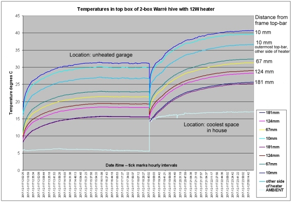
In the garage, inside hive temperatures averaged 21.7°C and ambient was 5.7°C.
Lumped enclosure thermal conductance = heater wattage / temperature differential inside minus outside = 12.5 / (21.7 - 5.7) = 0.75 watts per degree. In the house, the ambient temperature was 16.4°C and the average stable inside hive temperature was 31°C. This gives a lumped enclosure thermal conductance of 0.86 watts per degree.
Mitchell (2016) found that a cedar Warré with the same thickness walls and other features as used in this study had a lumped thermal conductance of 1.28 watts per degree. Possible causes of the discrepancy between this study and Mitchell's were sought. The wattage of the heater was verified with the help of a current sense resistor and Universal AvoMeter Model 8 multimeter. The sensors were validated as described elsewhere and found to be within half a degree of each other. In email correspondence with Mitchell he suggested that the type of heater may be the cause. He wrote that he used an aluminium plate which gives a lower temperature form of heating and that the hotter the air plume off the heater the greater the heat loss as the hot plume impacting the roof transfers heat to the roof faster than a cooler plume.
However, it is difficult to envisage this as the explanation of the discrepancy as a greater heat loss would result in a higher lumped thermal conductance, not one that is considerably lower than reported by Mitchell (2016). Even so it seems probable that differences in heater architecture and temperature could account for the discrepancy. The heater elements used in this study felt warm to the touch and the back of a finger could be rested on them without discomfort. Even if the lumped thermal conductance is dependent on heater design, as long as a the same heater is used throughout, the method should be valid for comparing various types of bee habitation as in the case of Mitchell's application.
It was assumed that a 2-box Warré was used by Mitchell (2016). However, the effect of adding a box underneath a 1-box Warré was investigated after initial temperature stabilisation. The joint between the boxes was sealed with tape. The result was a drop in average temperature of 0.8°C.
Reference
Mitchell, D. (2016). Ratios of colony mass to thermal conductance of tree and man-made nest enclosures of Apis mellifera: implications for survival, clustering, humidity regulation and Varroa destructor. International Journal of Biometeorology, 60(5), pp.629–638. Available at: http://dx.doi.org/10.1007/s00484-015-1057-z .